
Research on Model Reference Adaptive Control of NC Machining Process
According to the model reference adaptive control (MRAC) idea, the MRAC model of CNC machine tool cutting process was established, and then the dynamic process simulation of the model was established. At the same time, feedback closed-loop control and open-loop control of the machining process are simulated respectively, and the three kinds of simulation results are compared. From the simulation results, it can be seen that the MRAC machine tool cutting performance index is the best.
1 Working principle of CNC machine tool MRAC
The MRAC of numerically-controlled machine tools is a cutting process performed by a machine tool, a cutting tool, and a workpiece system. The basic structure of the control system is shown in Figure 1. In addition to the position and speed control loops of general CNC machine tools, it also adds MRAC feedback loop. When the system is disturbed by various random factors, the state parameters of the cutting process change immediately, and the values ​​of these parameters are detected at any time by the sensor and converted, in the MRAC control unit with the given evaluation index or constraint (ie, desired Performance indicators) to identify and compare, to obtain the performance index deviation, and then to the host CNC output correction signal, the input parameters of the system are corrected, so that the cutting process changes to the predetermined indicators and conditions in order to achieve the best state.
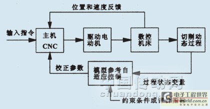
Figure 1 MRAC system structure of CNC machine tools
2 Establishment of MRAC model for machining of machine tools
The MRAC model of the machine tool cutting process is shown in Fig. 2. It is composed of a servo mechanism, a cutting process, a reference model adjustment mechanism, a feedforward device, and a feedback device.
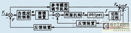
Figure 2 MRAC model block diagram of the cutting process
The servo link can be represented by a two-section system:
 (1)
(1)
Where: s is the operator of the Laplace transform; u is the servo input (V); Kn is the servo gain (mm/(V · s)); ωn is the natural frequency of the servo system (rad/s); Speed ​​(mm/s); ξ is the damping coefficient; f is the feed (mm/r) and can be expressed as:
 (2)
(2)
In the formula: n is the spindle speed (r/min); the household is the number of teeth of the cutter when milling, and p=1 when turning.
Considering that the reference model adjustment mechanism is an ideal performance indicator, the link is still the same as that of the servo mechanism.
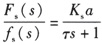
The static cutting force Fs of the cutting process can be expressed as:
 (3)
(3)
In the formula: Ks is the cutting specific force (N/mm2), m is the exponent (general m<1), Ks, m are all depend on the workpiece material and the shape of the tool; a is the amount of back eating knife (mm).
According to different process characteristics, Fs dynamic process can also be expressed by equation (3). Assuming m=1, the dynamic process can be represented by a first-order system:
 (4)
(4)
Where: Ï„ is a time constant.
The feedforward device and the feedback device in the model are proportional and the proportional coefficient is K.
Therefore, according to the composition of each of the above system links, the mathematical control model of the MRAC process shown in FIG. 3 can be obtained.
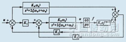
Figure 3 MRAC mathematical model of cutting process
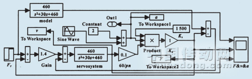
Figure 4 MRAC simulation
3 Machining performance of MRAC in machine tool machining
In the machining process, the cutting performance not only has a great impact on the quality of the parts, but also easily damage the tool. The cutting process of machine tools, cutting tools, and workpiece systems is an unstable process. It is often disturbed by many uncertainties outside the world, resulting in changes in the status parameters during the cutting process. If not adjusted in time, the cutting performance will be greatly reduced. Through MRAC adjustment, the cutting performance parameters can always be in a stable state. The constant cutting force in the machining process of the machine tool is used as an example to illustrate that the MRAC can adjust the cutting force in time with external factors (such as changes in the amount of back-to-eat knife) so that it is always at the desired cutting force. According to experiments, the known parameters Ks=1500N/mm2, n=600r/min, Kn=0.95mm/(V·s), ξ=0.68, p=1, m=1, ωn=22rad/s in the machining model, The back knife amount varies from 1 to 3 mm in a sinusoidal curve, and the desired cutting force setting value is 1000 N. The above parameters are used in the mathematical control model of FIG. 3, and the simulation diagram shown in FIG. 4 can be obtained by using the MATLAB/SIMULINK tool. The simulation result is shown in FIG. 5.
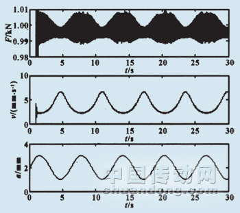
Figure 5 Simulation results
From the simulation results in Fig. 5, it can be seen that the change in the backing amount is just the opposite of the change in the feedrate, that is, if the backing amount increases, the feedrate is decreased to keep the cutting force constant at 1000N. Above, and vice versa. Therefore, the MRAC system achieves constant force control of the machining process by automatically and accurately adjusting the feed rate of the machining process.
4 Comparison of cutting performance between MRAC and conventional closed-loop and open-loop control
4.1 Cutting performance simulation of traditional closed-loop and open-loop control systems
Refer to MRAC simulation diagram 4 to establish the closed loop and open loop simulation diagrams respectively (open loop simulation diagram without feedback, other closed loop simulation, refer to closed loop diagram, this article has omitted). As shown in Figure 6, the simulation results are shown in Figure 7 and 8 shows. From the simulation results, it can be seen that the cutting force of the closed-loop control can basically make it constant at about 1000 N, while the cutting force of the open-loop control deviates far from 1000 N.
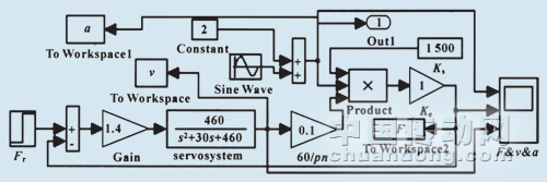
Figure 6 Closed-loop control simulation
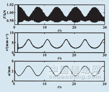
Figure 7 Closed-loop control simulation results 
Figure 8 Open-loop control simulation results
4.2 Analysis of Cutting Performance Errors among Three Control Systems
From the simulation results of the above three kinds of control charts, their machining and cutting performance errors can be roughly analyzed. First of all, the error of MRAC system can be roughly calculated:
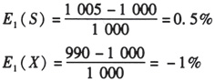
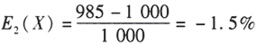
The error of the closed-loop control system can be obtained:

The error of open-loop control system can be obtained:
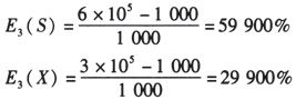
In the formula: E(X) and E(S) represent the upper and lower deviations of the error, respectively.
By comparison, it can be found that the MRAC system has the smallest error, so MRAC can maintain better cutting performance in machining than the traditional closed-loop and open-loop systems.
5 Concluding remarks
Through MATLAB/SIMULINK simulations and experiments, MRAC can keep the machining performance of CNC machine tools in a stable state. In view of this, MRAC can also be applied to other automation equipment. It should be noted that the conventional MRAC can only be applied to the minimum phase system, and the processing may be a non-minimum phase system under a certain sampling condition, with an unstable zero point, and a modified MRAC scheme is needed at this time.
Mainly applied for home textile machine, help to feed down automatically and clean quilt of dust on the cover.
We R&D automatic down loading machine which is the supplement of Down Filling Machine, to improve the working efficiency that just need one person to operate. Automatic cleaning machine is mainly aimed at home textile enterprises, which is used to clean the quilt. As well both machines could be customized according to customers' requirements.
Not only automatic down feeding machine but also automatic brushing machine can be used with automatic down filling machine and quilt folding machine, they help customer realize fully automatic production.
Automatic Down Feeding Machine,Auto Feeding Machine,Auto Sealing Machine,Small Section Of Conveyor,Belt Conveyor,Dust Removal System
Changshu Bealead Automatic Machine CO., LTD. , https://www.bealeadglobal.com