
Home Security System Design Based on CAN Bus
2 <br> <br> Overall constitution of the system block diagram shown in Figure 1. SCM control DTMF transceiver circuit, digital voice circuit, hook control circuit. The detector can quickly and accurately monitor the abnormal condition of the house, notify the controller in time after confirmation, and then the SCM controls the telephone interface circuit to realize analog off-hook, automatically dials a pre-set telephone number to perform voice alarm and informs the management center. . When the other party responds, the alert status is automatically restored.

3 <br> <br> hardware design system uses the main control section AT89S52 microcontroller without expanding the external memory. The watchdog circuit uses a programmable serial EEPROM-X25045. The X25045 stores data information such as the flag field, phone number, alert code, and system settings. The digital voice circuit uses a digital voice chip ISD1420. The ISD1420 in the system is only used as a basic recording and playback circuit, so all address lines are set to 0, so the starting address for playback is 0. The voice signal is picked up by the electret microphone and amplified by amplifiers inside the chip input from both ends of the MIC and the MICREF. The audio signal after the amplifier is used is connected with the talk circuit from the SP+ to send the voice signal.
3.1 The ring detection and analog pick-up hook unit system is at both ends of the telephone line and is in a monitoring state at all times, which will not affect the normal operation of the telephone. Ring detection is performed when the system receives a ring signal. The ringing signal is connected to the P3.4 port of the AT89S52 via three inverters. If no one answers after five rings, the system enters the automatic off-hook state. MCU P1.2 pin output high, transistor V501 conduction relay K1 action, the load resistance access circuit to achieve analog off-hook. After this, a current of more than 10 mA will appear on the telephone line. After the switching center detects this current, it will no longer output the ringing signal and will instead switch to the telephone. If the ringing signal does not reach the preset value and disappears, the count value of the microcontroller is cleared and the controller does not operate.
3.2 DTMF transceiver unit DTMF transceiver circuit using DTMF signal encoding / decoding chip MT8880 [5] chip, the microcontroller through the DTMF transceiver circuit to dial the phone number for telephone alarm, DTMF transceiver circuit shown in Figure 2.
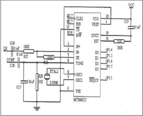
figure 2
The MT8880 provides an interface to the microprocessor to control its transmit, receive and operating modes. Its receiving part adopts the single-end input, is made up of R27, R28 and C16, its input voltage gain is 1, can adjust the gain of the input signal through changing R28. Its sending part consists of R29, C17, C18, and XTAL2. Its control part consists of R30 and C19. The IRQ/CP is connected to the P3.5 pin of the microcontroller. When the MT8880 receives a valid dual tone multi-frequency signal, the microcontroller interrupts processing. The IN side of the MT8880 is connected to the QR terminal of the talk circuit TEA1062, and the TONE side of the MT8880 is connected to the DTMF side of the TEA1062.
3.3 Talk Unit The talk circuit uses a telephone-only call integrated circuit TEA1062. When sending a call, the voice signal (from the ISD1420) is input through the MIC+ pin, and the DTMF signal (from the MT8880) is input through the DTMF pin, and after being amplified by the TEA1062, is sent from the LN pin to the telephone outside line. When receiving the call, the signal passes through the cancellation side tone network, is input from the IR pin, and is amplified and then output from the pin QR. The signal is divided into two ways: one is sent to the AN IN terminal of the ISD1420 for voice recording, and the other is sent to the IN-end of the MT8880. Extract the DTMF signal.
3.4 CAN bus data transmission unit CAN bus data transmission unit consists of two parts, one part is the CAN controller, to achieve the interaction and control of the bus data, and the other part is the CAN data transceiver, to achieve data network transmission.
MCU AT89S52 achieves access to the bus by controlling the CAN controller, and is also responsible for the measurement and control of the functional unit. The CAN bus interface circuit is shown in Figure 3.
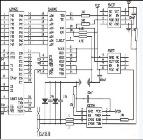
image 3
The AT89S52 accesses the CAN controller SJA1000 by means of interrupts. In order to enhance the anti-interference ability of the CAN bus node, the SJA1000 is connected to the CAN bus driver PCA82C50 through a high-speed optocoupler 6N137. The CANH and CANL pins of the PCA82C50 are each connected to a 5-resistor resistor connected to the CAN bus, which can act as a current limiter to protect the PCA82C50 from overcurrent surges.
4 <br> <br> software design software system is modular in design, includes the main program module, CAN communication module, a ringer detection module, a voice alarm module, the DTMF transceiver module, where the main program and introduces the CAN communication module design.
4.1 Main Program Design The main program mainly completes the call of each function module, detects system input, and then performs judgment processing according to the system state. Before the program performs the main loop, necessary initializations are performed, such as the MT8880, ISD1420, and SJA1000 flags. The main program flow is shown in Figure 4.
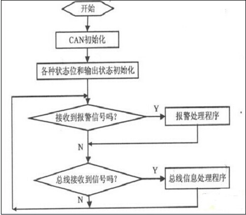
Figure 4
4.2 CAN Communication Module Design CAN communication module includes controller initialization, data receiving and sending subroutines. The SJA1000 has two states, reset mode and operating mode. The two states have different register configurations. After the parameters are set, the CPU issues a command and the SJA1000 is in a working state for normal communication. If communication fails, the CPU will put the SJA1000 back into reset mode. The receiving module is responsible for the receipt of the node message and related processing. During the receiving process, the CPU reads the data and judges the type of the data frame according to the command word for different processing. The sending module is responsible for the sending of the message. Before sending the data, the SJA1000 determines whether the sending condition is satisfied. If it is satisfied, the message frame information, the identifier, and the data to be sent are written into the buffer and can be sent. The JA1000 transceiver flow chart is shown in Figure 5.
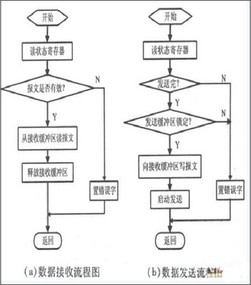
Figure 5
5 Conclusion <br> <br> The system AT89S52 microcontroller core, without any modification to the telephone network, to achieve the maximum security home point automatic detection and voice alarm. The design uses the CAN bus structure to form the security system, which has better flexibility and expandability. At the same time, it uses the CAN bus to introduce real-time data processing and improves the reliability of the system. Can have more application and promotion value for building video intercom, intelligent community management, access control management, etc.
High Temp Roof-mounted Cabinet Air Conditioner
Outdoor Enclosure Air Conditioner are designed for Power industry,Communication industry, Chemical industry or related industrial equipment applications of high-performance ac type air conditioning unit, cabinet internal devices suitable for heat, temperature sensitive, and inside and outside completely isolated applications;
Indoor Enclosure Air Conditioner DC48V Enclosure Air Conditioner High Temp Enclosure Air Conditioner
Outdoor Enclosure Air Conditioner Roof-Mounted Enclosure Air Conditioner Energy Storage Air Conditioner
The cabinet air conditioning refrigerates the air through inside and outside two independence, and exchanges the heat inside the cabinet to the outside by the heat-exchanger. By this way, it can protect the electricity wind chest's electrical element in the controllable temperature range movement. Simultaneously the cabinet air conditioning has dehumidifies the function, which will guaranteed the cabinet interior has the ideal temperature and the humidity.


1. Equipment cabin of Mini ICT room;
2. Equipment cabin of RRU outdoor cabinet;
3. Equipment cabin of 4G and 5G base station outdoor cabinet;
4..Equipment cabin of micro station outdoor cabinet;
5. Electric power outdoor cabinet;
6. Industrial control cabinet refrigerating;
7. Laboratory dedicated refrigerating;
8. Museum, wine cellar dedicated refrigeration;
9. Solar and wind power storage container;


High Temp Enclosure Air Conditioner, High Temp Cabinet Air Conditioner,High Temp air conditioner, Roof-mounted Cabinet Air Conditioner
Taizhou Tentcool Electrical Appliance Co., Ltd. , https://www.tentcool.com