
Application of Four-way Servo Control System on Molding Machine
Abstract: Disposable lunch box molding machine is a thermoforming machine. It is vacuum forming, compression molding, integrated molding and punching. It is used to process thermoformed plastic sheet. This article describes the application of the CA500 series heavy duty servo driver and the CM500 permanent magnet synchronous motor in a disposable lunch box molding machine. The servo system controls the stroke of the table, improves the positioning accuracy of the forming machine, and reduces the defective product rate.
Keywords: disposable lunch box molding machine, positioning control, CA500, CM500
First, the process introduction Disposable lunch box molding machine is a thermoforming machine, it sets vacuum molding, molding, comprehensive molding, punching into one, used to process thermoformed plastic sheet. Can be made into a variety of packaging containers: disposable fast food box, fish plate, supermarket plate, cake plate, KT plate, instant noodle bowl, foam plate and other products.
Process flow: As shown in Figure 1, the overall process flow is divided into: feeding - sheet into the forming machine - preheating - heating - forming - blanking - blanking - finished - packaging - Scraps were rolled up.

A working cycle of the molding machine includes the following actions:
(1) Feeding and sheet feeding machine: The foamed sheet is pulled to the inside of the sheet forming machine, and the feeding length is controlled by a photoelectric switch;
(2) Preheating and heating: The foamed sheet is preheated with a ceramic radiant tile, and the intelligent temperature control table controls the temperature to make it plastic;
(3) Molding: Hydraulically controls the upper and lower molds, vacuum, air pressure, and molding;
(4) Punching: Hydraulic automatic control punching, cutting the formed products into finished products;
(5) blanking, finished products, packaging: packaging of blanked finished products;
(6) Scrap Reeling: The remaining scrap left after punching is collected and recycled into the waste crushing granulator for reuse.
Second, the program description 1, process requirements:
In order to ensure the accuracy of the disposable lunch boxes entering the blanking stage after molding, and to increase the production efficiency as much as possible, the molding machine has the following technical requirements:
(1) The transmission process needs rapid acceleration and deceleration, acceleration and deceleration is less than 0.5S;
(2) When the disposable lunch box reaches the blanking position, the positioning speed is faster, and the positioning time is less than 1 second;
(3) In order to ensure the accuracy of punching, high positioning accuracy, position accuracy is less than 1mm;
(4) There is a signal output after the positioning is completed, and follow-up actions are performed with the PLC.
2. The servo control system is based on the process requirements of the molding machine, and uses the Quadra CA500 servo drive and the CM500 synchronous motor as the driving platform to design the following application solutions:
Servo driver: Quad CA500 heavy duty servo driver;
Servo motor: Quartet CM500 permanent magnet synchronous motor;
Other accessories: resolver card, IO expansion card, encoder shielded cable (9pin).
(1) The acceleration and deceleration time of the CA500 servo driver can reach a minimum of 0.1s, which can fully meet the requirements for the acceleration and deceleration of the lunch box forming machine in the transmission process;
(2) CA500 has built-in servo control function, built-in two-stage PID parameters, and can choose different PID parameters to perform according to position deviation, and has excellent servo motor control algorithm, can take advantage of the rapid response characteristics of servo motor and ensure the Positioning response speed;
(3) The CA500's servo positioning function is controlled by an external high-speed pulse. According to the actual mechanical displacement and the corresponding number of pulses, the electronic gear ratio is converted to achieve a very high positioning accuracy.
(4) Using CA500's internal multi-function terminal output function, when the positioning is completed, a signal is output to the PLC, notifying the PLC that the positioning has been completed to perform the next step.
Figure 2 shows the application scheme block diagram:
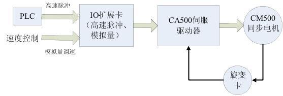
figure 2
3ã€Features of the Quartet Servo Control System (1) The CA500 servo drive is designed based on a large margin hardware platform and can be operated with 120% heavy load for a long period of time with strong overload capacity.
(2) CA500 driver can choose two positioning signal given mode, can use high-speed pulse given and analog quantity given;
(3) CA500 series built-in braking unit, users can configure the braking resistor as needed to achieve rapid braking effect;
(4)Flexible and powerful scalable platform, through the matching of the resolver card and IO expansion card, to meet various different process site requirements;
(5) The excellent servo motor control algorithm can not only drive the synchronous motor common in the industry, but also optimize the algorithm for CM500 synchronous motor, and give full play to the fast response characteristics and stability of the servo system that is used together;
(6) Double PID control selected based on position deviation to realize highly accurate and highly responsive position control.
Third, debug and explain 1, debug wiring diagram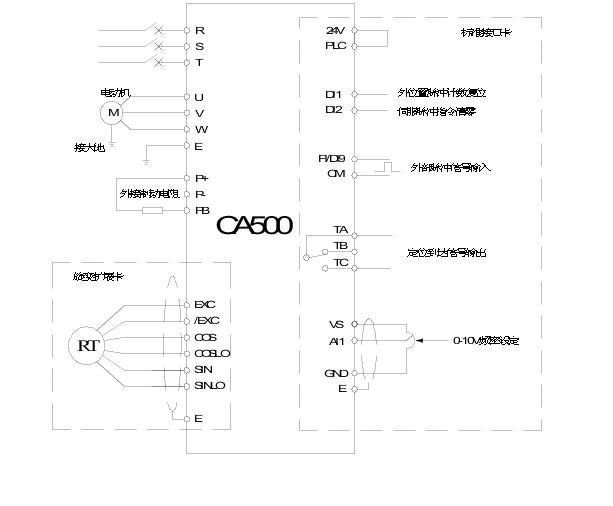
image 3
2. Set the servo control positioning function (1) Set the servo control function Fb.2.23 servo control function to 0001 is always valid.
(2) Select position pulse count reset terminal and servo command pulse value clear terminal (function number is 66, 77 respectively). For example, select terminals DI1 and DI2, then F3.0.00=66 and F3.0.01=77.
(3) Set the distance Fb.2.22 per revolution of the PG speed measuring shaft. The function of this parameter is to display the accumulated displacement in d1.2.20 and not to participate in the actual control calculation.
(4) Set the servo control position setting source Fb.2.24, set to 1 that the position is controlled by the high speed pulse, and set to 3 that the position is controlled by the analog quantity, which can be selected according to actual needs, and here is set to 1.
(5) Set the electronic gear ratio Fb.2.27, Fb.2.28. The electronic gear ratio maps the actual displacement per pulse to the manually determined displacement per pulse.
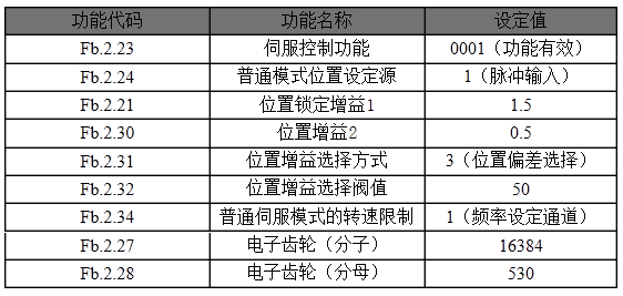
3, parameter setting (1) general function debugging:

(2) Servo positioning function debugging:
4. After the debugging operation, the pulse input is used as the position source mode. Before the operation, the DI1 terminal needs to be closed once to reset the position pulse accumulation count (D1.2.19, D1.2.18). Press FWD to start the servo driver, the motor will determine the motor running distance according to the number of pulses received from the DI9 terminal. The pulse speed and the speed limit of Fb.2.34 determine the running speed of the motor. The pulse source received by the DI9 terminal can be accumulated. Saved, the accumulated pulse number can be cleared by closing the DI4 terminal once.
5. Pay attention to (1) Position gain selection mode. When the gain is selected by position deviation (Fb.2.31=3), when the position deviation is less than the set pulse value (Fb.2.32), position gain 1 (Fb.2.21) is valid. . Otherwise, the position gain 2 (Fb.2.30) is valid.
(2) Responsiveness can be improved when the position gain is large, and overshoot, vibration, and noise are caused by excessive assembly.
(3) Adjusting speed closed loop Proportional gain F8.1.21 can suppress motor vibration.
(4) The speed limit mode of common servo mode Fb.2.34 is set to 1 frequency setting channel, which means that the motor rotation speed is controlled by the frequency channel only when the frequency of the external pulse is greater than the frequency of the frequency setting channel, otherwise the motor speed is affected by External pulse frequency control.
(5) Stop and restart when switching from speed mode to servo control.
IV. Summary This article describes the application of the four-party CA500 heavy-duty servo driver and CM500 permanent-magnet synchronous motor in a disposable meal box molding machine. The application program has high precision and rapid response, which can ensure the quality of the production lunch box to the maximum extent, reduce the defective product rate, and solve the production cost.
References 1, "CA500 Series Heavy Duty Servo Drive Manual V1.1" Shenzhen Sifang Electric Technology Co., Ltd. 2, "CM500 AC Permanent Magnet Synchronous Motor Manual" Shenzhen Sifang Electric Technology Co., Ltd. 3, "I/O Expansion Card User's Manual (IOA-B100 Standard Type)" Shenzhen Sifang Electric Technology Co., Ltd.
Keywords: disposable lunch box molding machine, positioning control, CA500, CM500
First, the process introduction Disposable lunch box molding machine is a thermoforming machine, it sets vacuum molding, molding, comprehensive molding, punching into one, used to process thermoformed plastic sheet. Can be made into a variety of packaging containers: disposable fast food box, fish plate, supermarket plate, cake plate, KT plate, instant noodle bowl, foam plate and other products.
Process flow: As shown in Figure 1, the overall process flow is divided into: feeding - sheet into the forming machine - preheating - heating - forming - blanking - blanking - finished - packaging - Scraps were rolled up.
figure 1
A working cycle of the molding machine includes the following actions:
(1) Feeding and sheet feeding machine: The foamed sheet is pulled to the inside of the sheet forming machine, and the feeding length is controlled by a photoelectric switch;
(2) Preheating and heating: The foamed sheet is preheated with a ceramic radiant tile, and the intelligent temperature control table controls the temperature to make it plastic;
(3) Molding: Hydraulically controls the upper and lower molds, vacuum, air pressure, and molding;
(4) Punching: Hydraulic automatic control punching, cutting the formed products into finished products;
(5) blanking, finished products, packaging: packaging of blanked finished products;
(6) Scrap Reeling: The remaining scrap left after punching is collected and recycled into the waste crushing granulator for reuse.
Second, the program description 1, process requirements:
In order to ensure the accuracy of the disposable lunch boxes entering the blanking stage after molding, and to increase the production efficiency as much as possible, the molding machine has the following technical requirements:
(1) The transmission process needs rapid acceleration and deceleration, acceleration and deceleration is less than 0.5S;
(2) When the disposable lunch box reaches the blanking position, the positioning speed is faster, and the positioning time is less than 1 second;
(3) In order to ensure the accuracy of punching, high positioning accuracy, position accuracy is less than 1mm;
(4) There is a signal output after the positioning is completed, and follow-up actions are performed with the PLC.
2. The servo control system is based on the process requirements of the molding machine, and uses the Quadra CA500 servo drive and the CM500 synchronous motor as the driving platform to design the following application solutions:
Servo driver: Quad CA500 heavy duty servo driver;
Servo motor: Quartet CM500 permanent magnet synchronous motor;
Other accessories: resolver card, IO expansion card, encoder shielded cable (9pin).
(1) The acceleration and deceleration time of the CA500 servo driver can reach a minimum of 0.1s, which can fully meet the requirements for the acceleration and deceleration of the lunch box forming machine in the transmission process;
(2) CA500 has built-in servo control function, built-in two-stage PID parameters, and can choose different PID parameters to perform according to position deviation, and has excellent servo motor control algorithm, can take advantage of the rapid response characteristics of servo motor and ensure the Positioning response speed;
(3) The CA500's servo positioning function is controlled by an external high-speed pulse. According to the actual mechanical displacement and the corresponding number of pulses, the electronic gear ratio is converted to achieve a very high positioning accuracy.
(4) Using CA500's internal multi-function terminal output function, when the positioning is completed, a signal is output to the PLC, notifying the PLC that the positioning has been completed to perform the next step.
Figure 2 shows the application scheme block diagram:
figure 2
3ã€Features of the Quartet Servo Control System (1) The CA500 servo drive is designed based on a large margin hardware platform and can be operated with 120% heavy load for a long period of time with strong overload capacity.
(2) CA500 driver can choose two positioning signal given mode, can use high-speed pulse given and analog quantity given;
(3) CA500 series built-in braking unit, users can configure the braking resistor as needed to achieve rapid braking effect;
(4)Flexible and powerful scalable platform, through the matching of the resolver card and IO expansion card, to meet various different process site requirements;
(5) The excellent servo motor control algorithm can not only drive the synchronous motor common in the industry, but also optimize the algorithm for CM500 synchronous motor, and give full play to the fast response characteristics and stability of the servo system that is used together;
(6) Double PID control selected based on position deviation to realize highly accurate and highly responsive position control.
Third, debug and explain 1, debug wiring diagram
image 3
2. Set the servo control positioning function (1) Set the servo control function Fb.2.23 servo control function to 0001 is always valid.
(2) Select position pulse count reset terminal and servo command pulse value clear terminal (function number is 66, 77 respectively). For example, select terminals DI1 and DI2, then F3.0.00=66 and F3.0.01=77.
(3) Set the distance Fb.2.22 per revolution of the PG speed measuring shaft. The function of this parameter is to display the accumulated displacement in d1.2.20 and not to participate in the actual control calculation.
(4) Set the servo control position setting source Fb.2.24, set to 1 that the position is controlled by the high speed pulse, and set to 3 that the position is controlled by the analog quantity, which can be selected according to actual needs, and here is set to 1.
(5) Set the electronic gear ratio Fb.2.27, Fb.2.28. The electronic gear ratio maps the actual displacement per pulse to the manually determined displacement per pulse.
3, parameter setting (1) general function debugging:
(2) Servo positioning function debugging:
4. After the debugging operation, the pulse input is used as the position source mode. Before the operation, the DI1 terminal needs to be closed once to reset the position pulse accumulation count (D1.2.19, D1.2.18). Press FWD to start the servo driver, the motor will determine the motor running distance according to the number of pulses received from the DI9 terminal. The pulse speed and the speed limit of Fb.2.34 determine the running speed of the motor. The pulse source received by the DI9 terminal can be accumulated. Saved, the accumulated pulse number can be cleared by closing the DI4 terminal once.
5. Pay attention to (1) Position gain selection mode. When the gain is selected by position deviation (Fb.2.31=3), when the position deviation is less than the set pulse value (Fb.2.32), position gain 1 (Fb.2.21) is valid. . Otherwise, the position gain 2 (Fb.2.30) is valid.
(2) Responsiveness can be improved when the position gain is large, and overshoot, vibration, and noise are caused by excessive assembly.
(3) Adjusting speed closed loop Proportional gain F8.1.21 can suppress motor vibration.
(4) The speed limit mode of common servo mode Fb.2.34 is set to 1 frequency setting channel, which means that the motor rotation speed is controlled by the frequency channel only when the frequency of the external pulse is greater than the frequency of the frequency setting channel, otherwise the motor speed is affected by External pulse frequency control.
(5) Stop and restart when switching from speed mode to servo control.
IV. Summary This article describes the application of the four-party CA500 heavy-duty servo driver and CM500 permanent-magnet synchronous motor in a disposable meal box molding machine. The application program has high precision and rapid response, which can ensure the quality of the production lunch box to the maximum extent, reduce the defective product rate, and solve the production cost.
References 1, "CA500 Series Heavy Duty Servo Drive Manual V1.1" Shenzhen Sifang Electric Technology Co., Ltd. 2, "CM500 AC Permanent Magnet Synchronous Motor Manual" Shenzhen Sifang Electric Technology Co., Ltd. 3, "I/O Expansion Card User's Manual (IOA-B100 Standard Type)" Shenzhen Sifang Electric Technology Co., Ltd.
Corn Thresher,Corn Sheller,Hand Corn Sheller,Corn Sheller Machine
Hunan Xinta Machinery Manufacturing Co., Ltd. , http://www.xyagriculture.com